Heathkit OL-1 Oscilloscope Rebuild
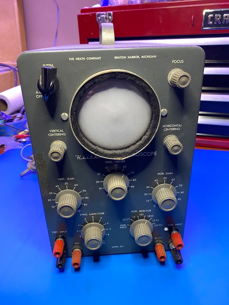
I picked up this Vintage Heathkit Oscilloscope for less than what it cost to have it shipped to me. At 0.4MHz it doesn't have the bandwith to be a highly accurate piece of gear to take measurements on, it will nonetheless be a fun restoration process, look great on the bench and should be able to provide some useful information to me.
As you can see above, while relatively dirty, it did arrive in decent condition. Due to the age of components and extremely lethal voltages in this scope, I wouldn't dream of turning it on before a complete restoration. Let's see what we have under the hood.
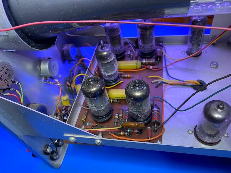
The inside of the case is full of dust, but I'm excited to not find any dead critters.
Surface dust/debris is all over the inside.
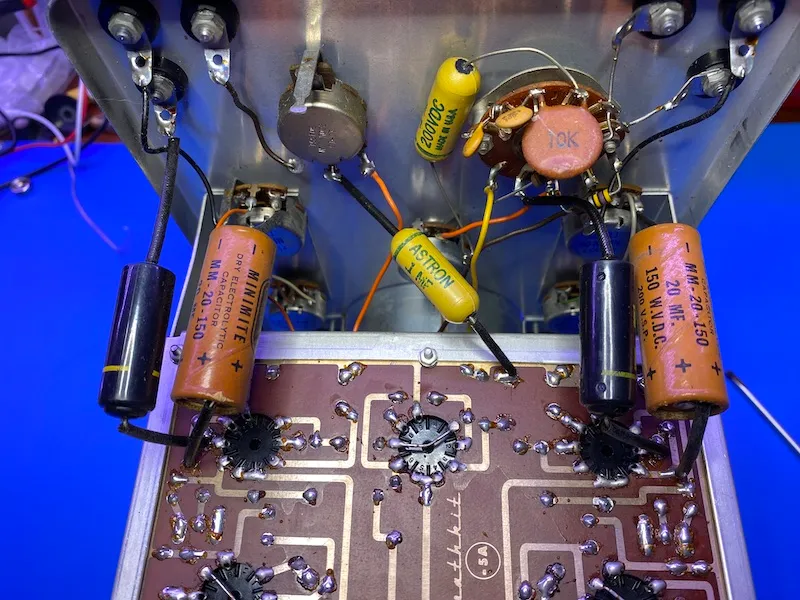
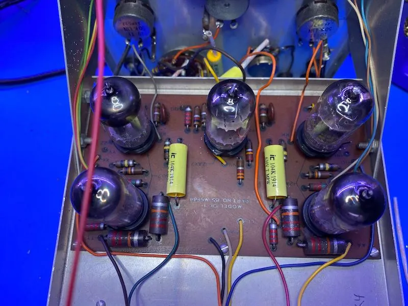
Overall, given this was a "kit" that someone put together, it seems they did take their time and put thought into wiring/soldering. At first glance, I don't see anything burned or cold/missing solder joints.
Plan of attack
Before I do anything, I plan to clean this unit thoroughly. It is no fun working on extremely grimey gear. While I'm doing that, I'll hit all of the potentiometers hard with some DeoxIt, as a few of them feel pretty gunked up.
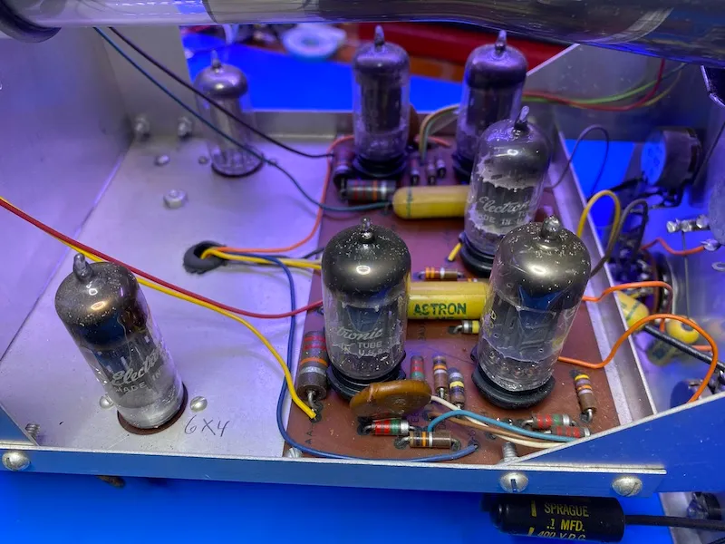
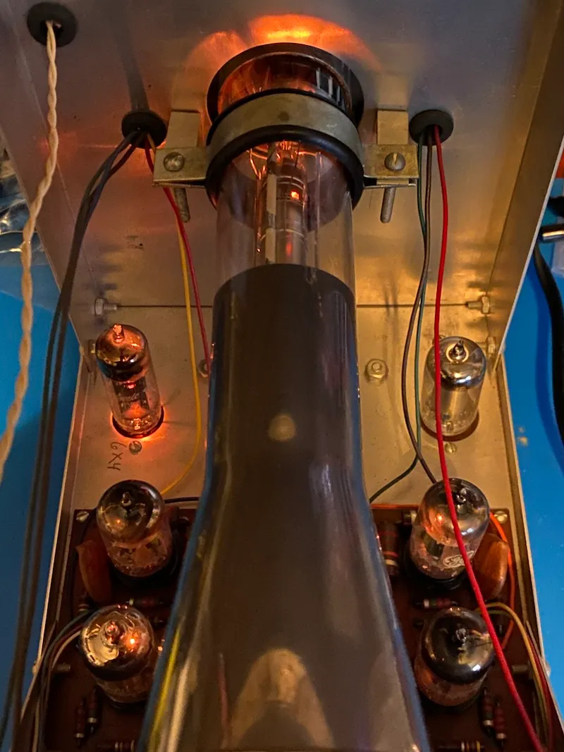
I very carefully cleaned the top of the 12A(U/X)7 and rectifier tubes just to get some surface dirt off of them. They all test as NOS. I don't think this unit has really been used.
Next up
- Power Supply Rebuild
- Replace all old wax & electrolytic capacitors. They actually test spot-on for capacitance, but are well past their life expectancy.
- Test resistors to ensure they are within tolerance & replace as necessary.
Power Supply Rebuild
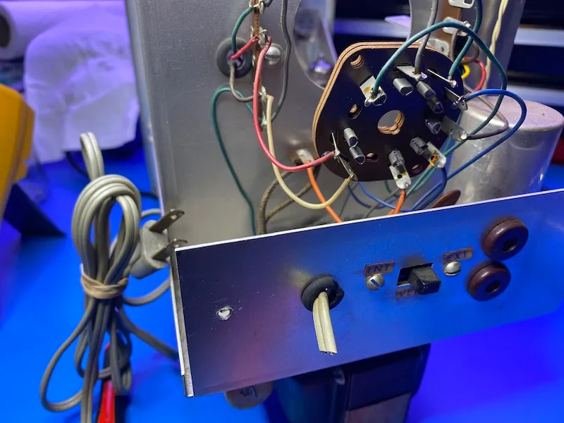
With vintage equipment like this, the best thing to do when you're starting out on it is to snip off the existing line cord. New ones are cheap, and it is for everyones safety to put on a polarized two prong cord. This way we up our chances of switch being on the "hot" leg to 99.9999% (assuming our wall outlets were properly wired), vs 50/50 if a non-polarized plug is still on the unit.
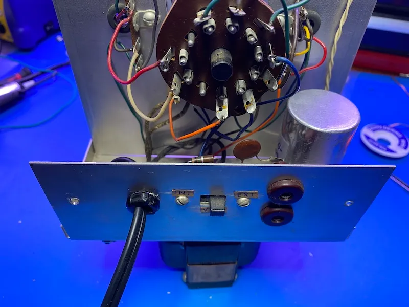
Next up, I ordered a new 20/20/20/20 @ 450V can capacitor from Antique Electronic Supply. While I could do this far more cheaply with some regular 'ole electrolytics, I think this looks far better, as it retains the original look. AES/CE Dist make these can capacitors on the original Mallory Equipment, so it is a drop-in replacement.
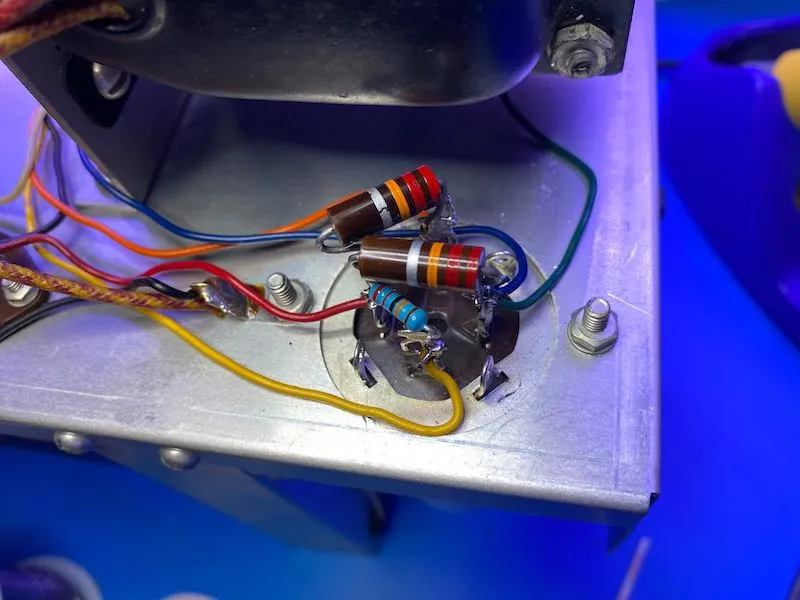
It fit perfectly. I swapped out the 220k resistor as it had drifted high. I managed to not mangle up the big 22k resistors too badly, and while not my best soldering work by a long shot it went back together nicely.
A new two prong polarized power cord was added with a Heyco strain relief. The old grommet was so hard, it fell apart with just a bit of pressure.
Capacitor/resistor replacement
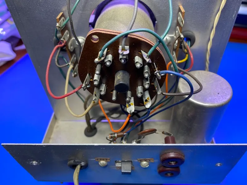
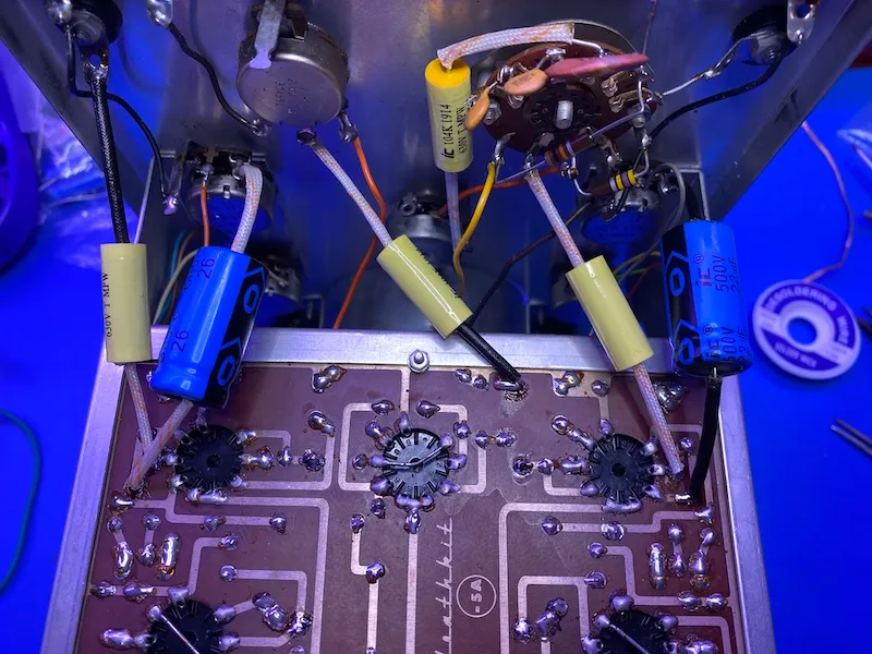
I replaced all of the .1 µF capacitors with 630V IC caps & added new high voltage caps in the CRT power supply.
New electrolytics
Wrapping up
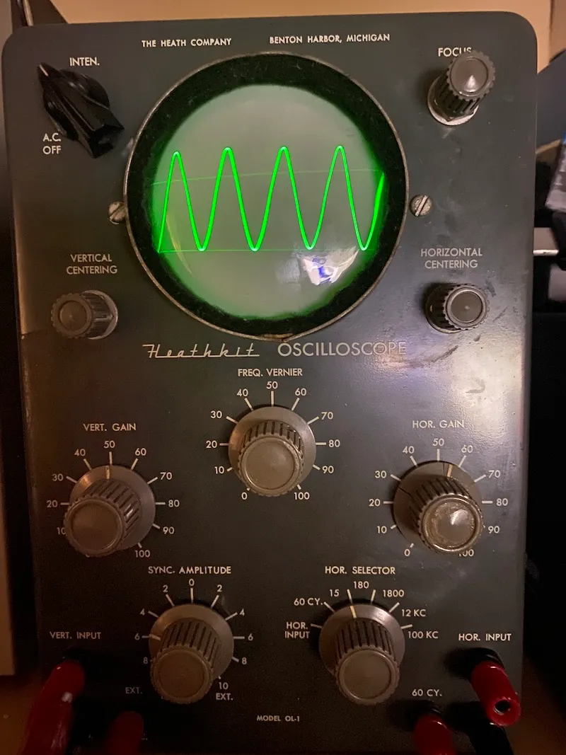
After the CRT was cleaned and reinstalled, I slowly brought up power to 117V on a variac, and it came alive!
It makes a decent trace!
I'm considering trying the curve tracer project on Mr. Carlson's patreon, but that is another project for another day. For now, I'm going to enjoy giving new life to a really old piece of equipment.