McIntosh MC240 Restoration
I've been keeping an eye on the auction site for an MC240. A few months ago, I purchased one in a state of disrepair that was appealing to me and a price I was comfortable with. I love the MC30s I rebuilt, but more is better, right?
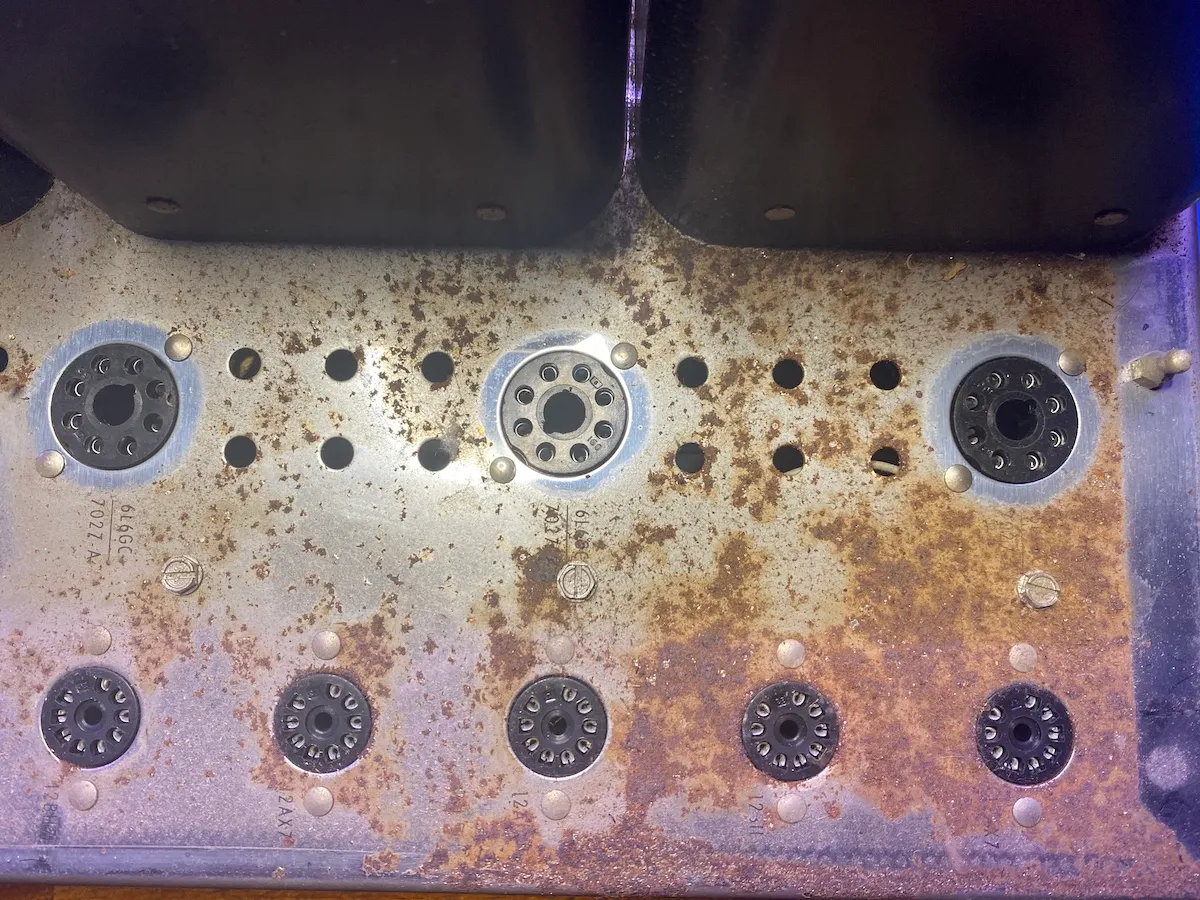
Here are some photos of what I was starting with. As you can see, it is a good thing that I didn't immediately plug the power in. The thermister had distegrated during shipping, and a capacitor with a weak solder joint had broken off of the tag board.
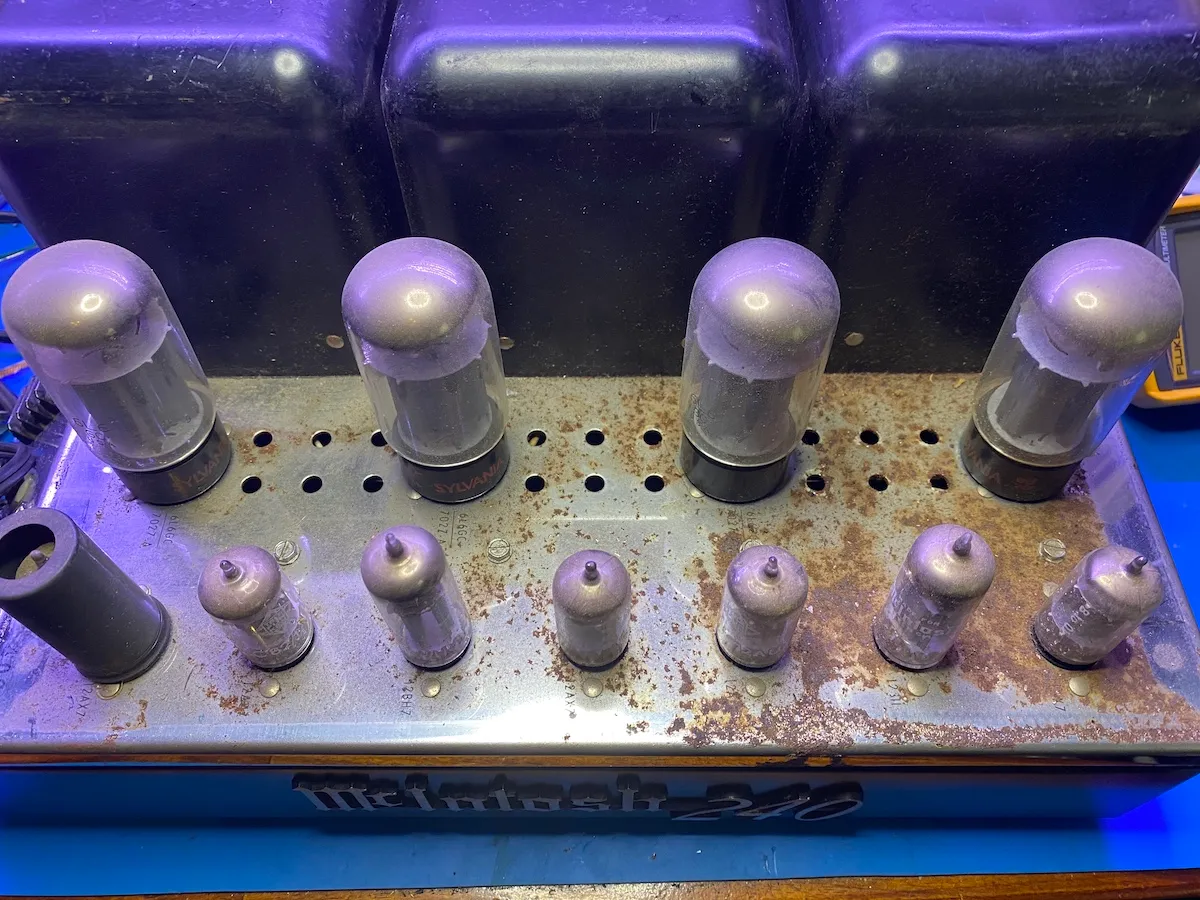
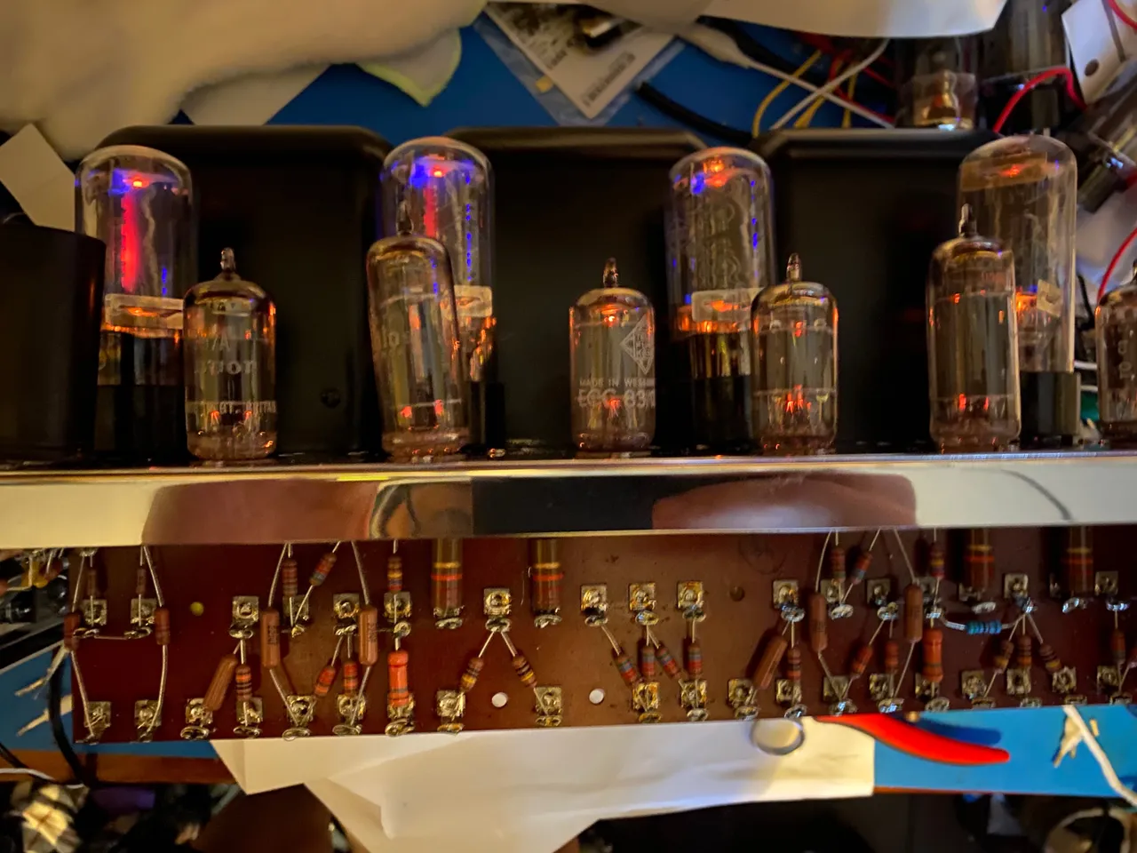
Pretty exciting looking right? For those of you keeping score, the 12AX/AU7 tubes are all Telefunken smooth plates. They tested darned near 100% on my Hickok tube tester. The 12BH7s are also original McIntosh branded, and test perfect. The power tubes are likely not original, and unfortunately, one had a piece of metal rolling around in the tube. The other three test okay, so I need to find a replacement Sylvania to have a working quad. I think there's a lot of life left in the other three.
I want this to look and sound amazing for years to come, so I have my work cut out for me.
Plan of Attack
I only planned on keeping the bottom chassis, transformers, pots, tag board & chassis logo. Everything else had to go.
- Strip and repaint the transformers.
- New top chassis from eBay.
- Strip and powder coat the bottom chassis.
- All new capacitors
- All new resistors
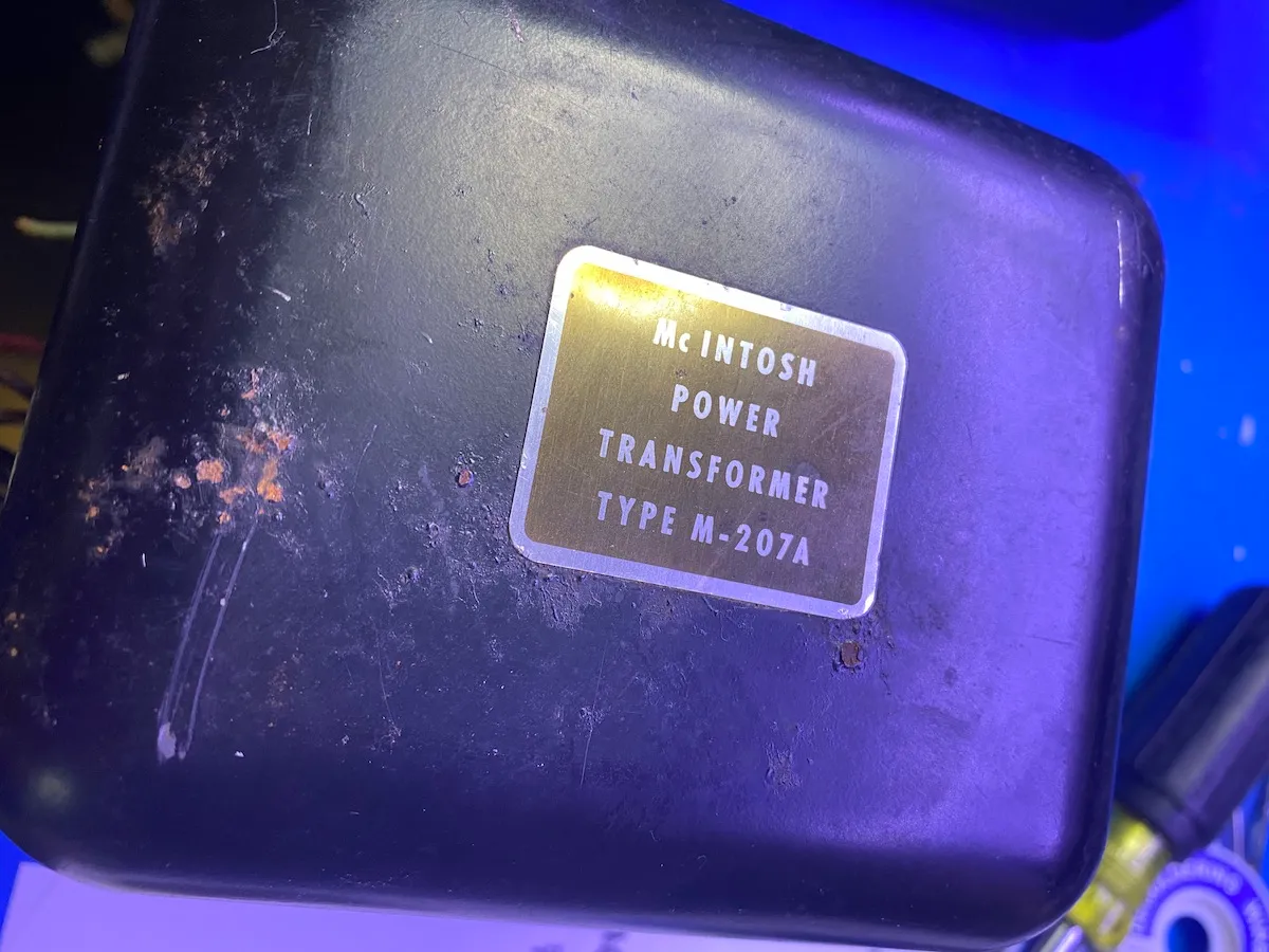
Transformer
I really don't like painting things. My paint booth is the great outdoors. However, since these are starting to show signs of rust, I want to attack it head on and stop it before it gets worse.
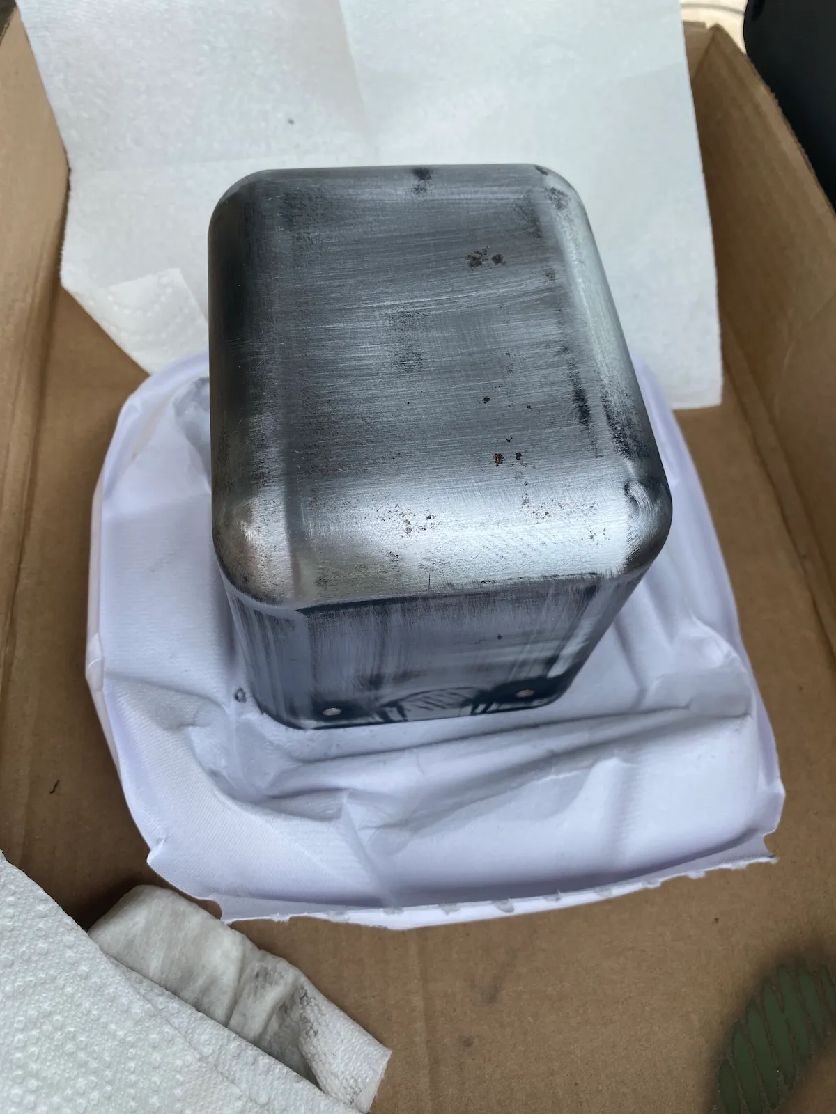
The original paint came off easily with a combination of 120 & 220 grit sandpaper.
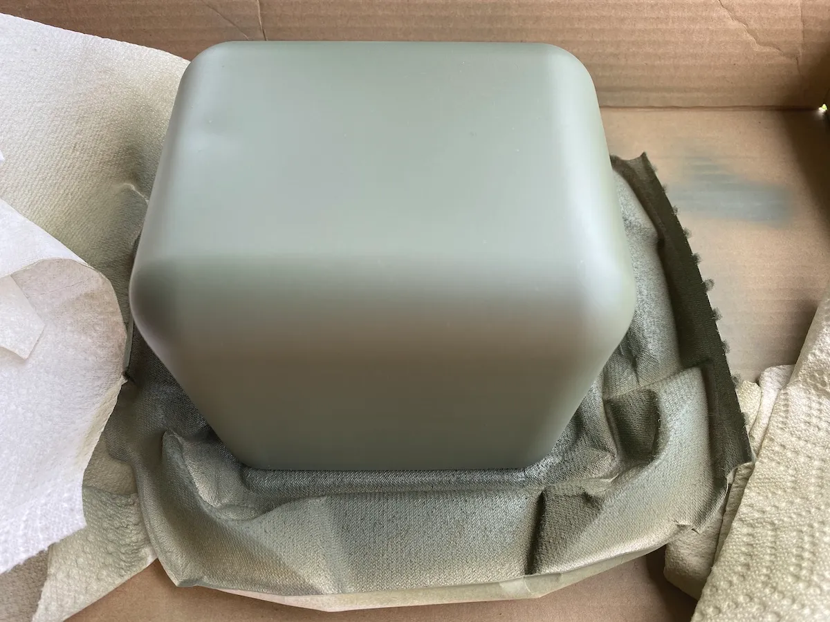
Primed it with an automotive etching primer.
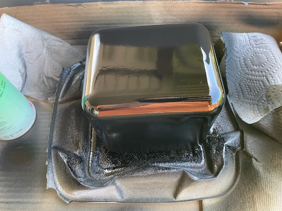
This is a photo right after I hit the last coat of black.
For my first disaster of the project. It was simply too hot outside and there was too much sun on my back porch. Even though I let the transformers sit for over a week before mounting them to the chassis, the paint was too soft. Things would stick to it, and it would easily dent. THIS IS WHY I HATE PAINTING THINGS! This meant having to repaint them yet again.
At this point, they look great.
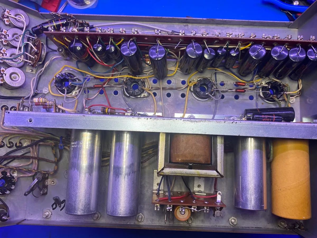
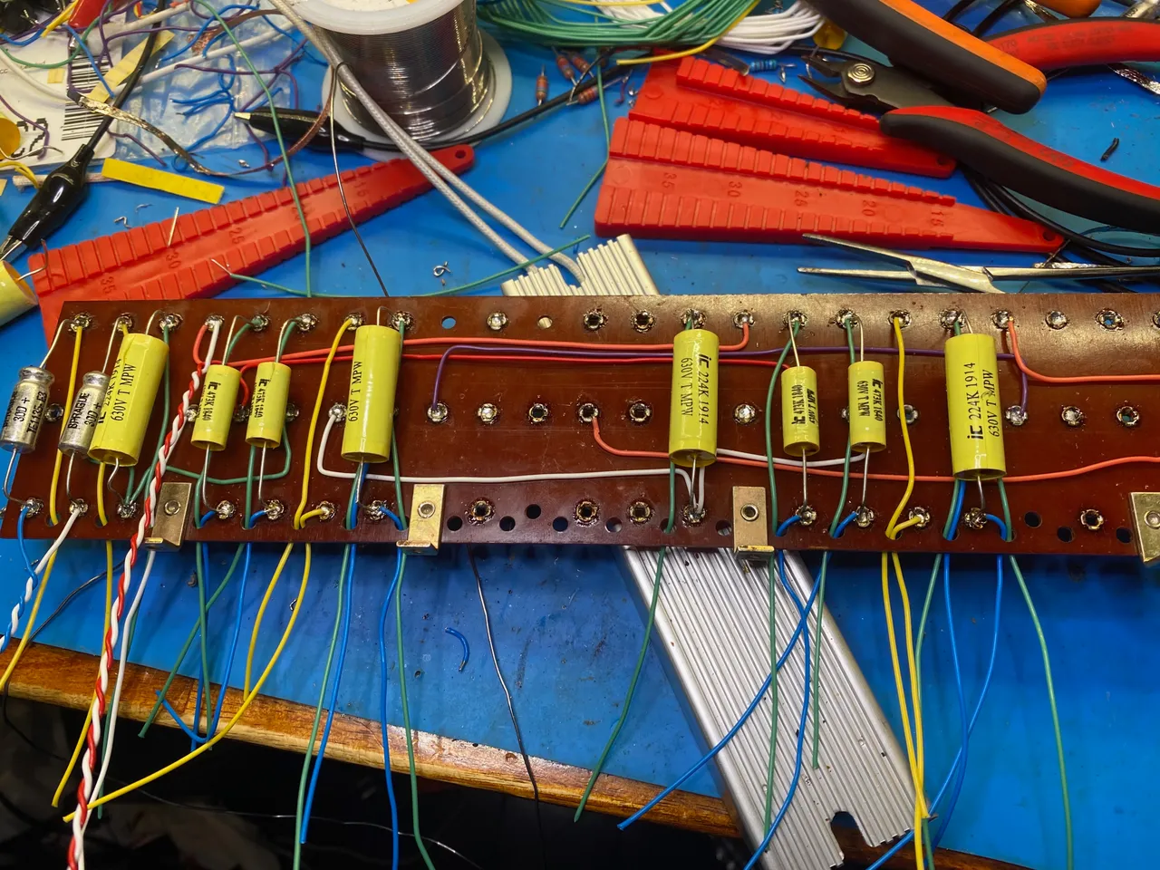
Rebuilding the tag board
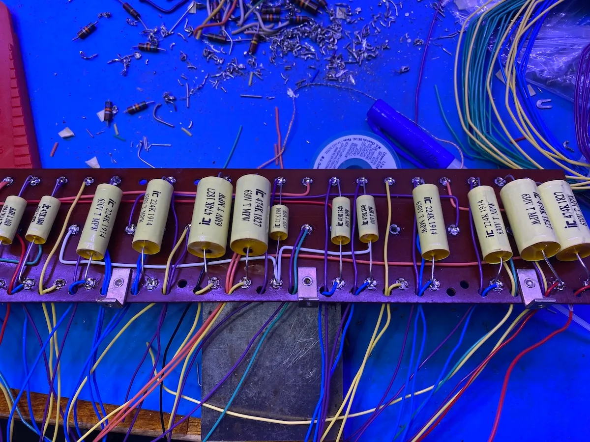
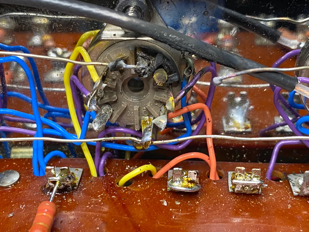
I used 600V rated wire from ApexJr and decided to use IC MPW capacitors for all of the coupling caps. Surprisingly, some of the original bumblebee caps didn't leak at 450V, but it is just a matter of time. I want to enjoy this amplifier for years to come, so probably to the dismay of guitar players, the bumblebee caps ended up in the bottom of the trashcan. Some people seem to like leaving the Sprague "Black Beauty" capacitors in, as they typically don't get leaky, but I chose to dump them as well. I found the outside foil end of the caps, and originally thought I installed them correctly, but I ended up being completely backwards. I fixed that after my disaster (more to come on that).
In my MC30 restoration, I went with relatively high end capacitors, and I'm honestly not sure if they make that much of a difference. I might experiment with different caps in this if the bug hits me, but in the meantime, I just want to listen to music.
I primarily used Vishay CCF60 Resistors on this build. They are high quality, and sound great. I originally tried to reuse the 2 watt Allen Bradley resistors, but they had drifted too far, and I replaced them with with modern Vishays. For value over 1Meg, I had to use resistors other than CCF60s. Also, I think due to Covid, I was unable to get enough CCF60 56k resistors, so I ended up swapping them all out for KOA Speer Metal Film resistors.
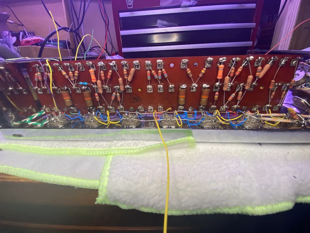
After a few hours of wiring everything up, I verified resistance as per the service manual. Everything was spot on, so I figured I was good to go! This is where the major annoyances on the project started.
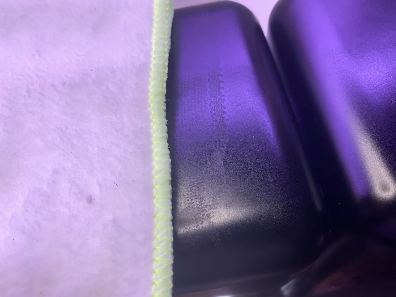
I flipped the amp over to insert the tubes and found this. I was really heart broken knowing I needed to repaint the transformers.
This is where things started to go down hill.
Woe is me.
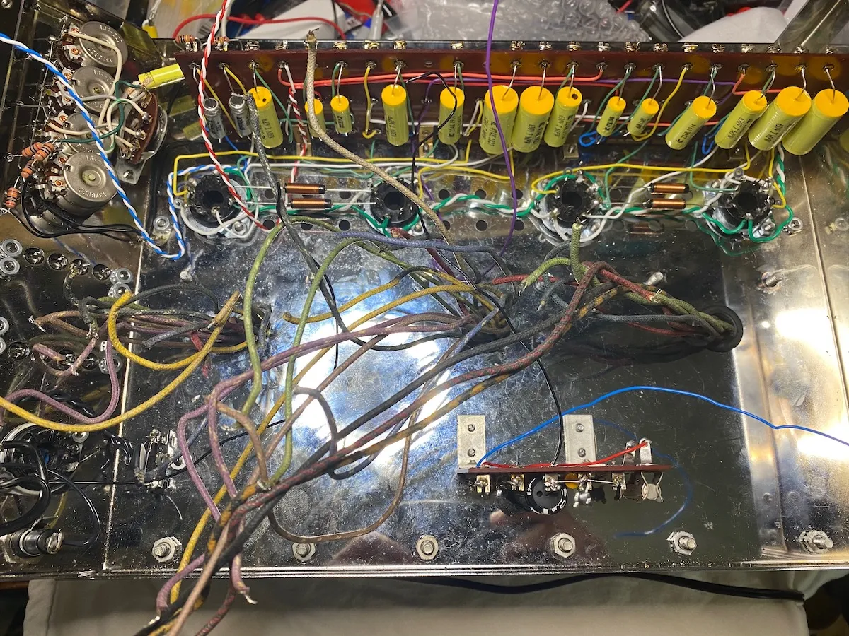
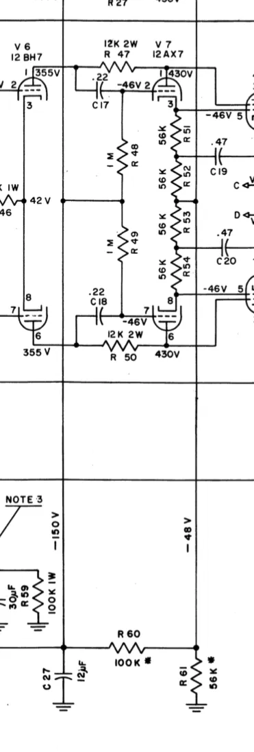
I'm still very new at all of this, and reading that schematic, I inserted the -150V bias supply on the board between the 1M resistors that goes to the grids on V7. A 100K resistor is also here and that supplies the -48V for the cathodes & output tubes. The crazy thing here is I got absolutely no voltage drop with tubes in, so the tubes where all being blasted with -150VDC. I went through everything thinking I had done something stupid, but finally found a post on AudioKarma where the author said there was a mistake, and that the -150V & -48 Volt rails were backwards. So I changed it to put the -150V rail in the 56k network, and voltages fell into place.
Now it starts to get weirder!
I have a shiny "new to me" quad of GE 6L6GCs, I didn't want to use for testing, so I used some old Soviet-era equivalents. These would start to red plate pretty quickly with moderate gain, but only in the left channel!
Hours where spent trying to troubleshoot this. After I swapped the old Russian tubes out for some new Tung-Sol 6L6GCs, I got more gain and no more red-plating, but things didn't get better. On the right channel, I'd use a 1khz sine wave into an 8 ohm load and I got about 40-42 clean watts of output when it was turned up all the way. Not bad! But in the left channel, the tubes would start internally arcing when the volume was turned up to about 11 o'clock. With music, it would pop with any kind of bass drum hit.
I really think troubleshooting problems is a lot of fun, and I was determined to figure it out. Afterall, once I have it, it will be experience I can carry forward! It had to be a mis-wiring somewhere. After verifying voltages, resistances, continuity of the circuit over and over, rewriring the output tube sockets umpteen times, I couldn't find it. I started pulling tubes, and trying to scope along the way to figure out where the problem was, then I made a huge mistake. I didn't shut the amp down when moving my scope probe and I shorted the plate to the heaters on the cathode follower tube of the left channel.
I did this to a pretty much NOS smooth plate Telefunken 12AX7. I blew out the burning bus wire, turned off power, pulled the plug and left it for about two weeks.
Getting back to it
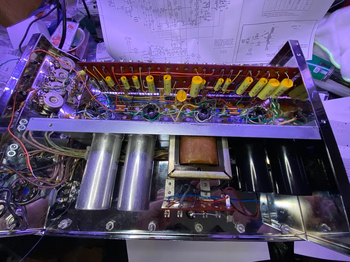
After decompressing for a couple of weeks, I decided to test the tubes, transformers & my old Tektronix 465 oscilloscope. I was terrified I took them out.
Everything was just fine! I dodged a huge bullet, and learned a valuable lesson. Now it was time to rewire everything, and this time do a better job.
I pulled all of the capacitors and wire off the tag board and started rewiring everything.
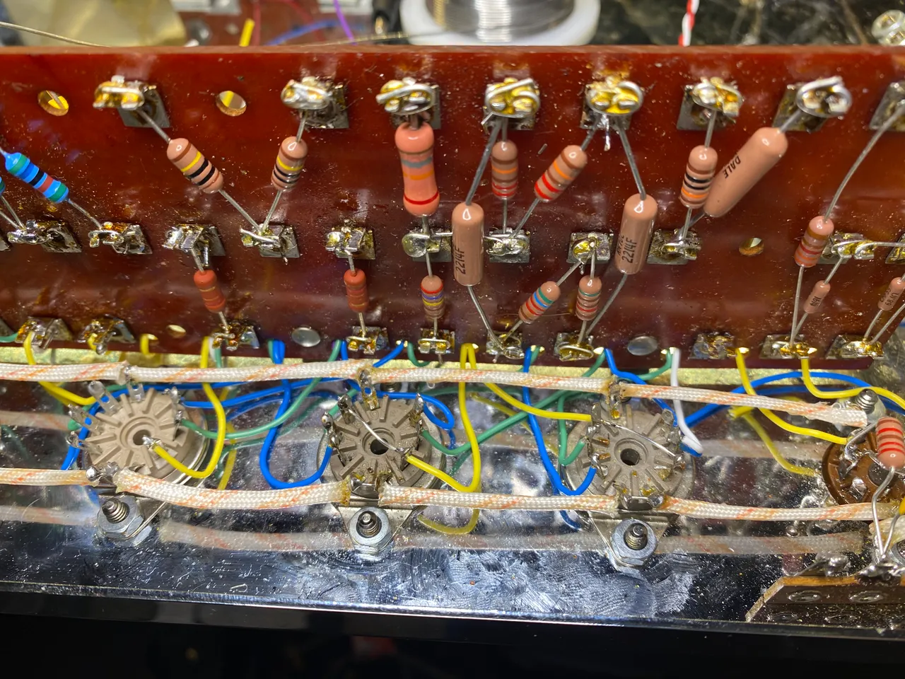
After everything was done, I verified wiring against the schematic, and brought the amp up slowly on the variac with a dim bulb tester. This time, everything worked perfectly!
It is really frustrating because I'm not sure what I originally did wrong, or how I could have found it. Now let's get onto the fun stuff.
Impressions
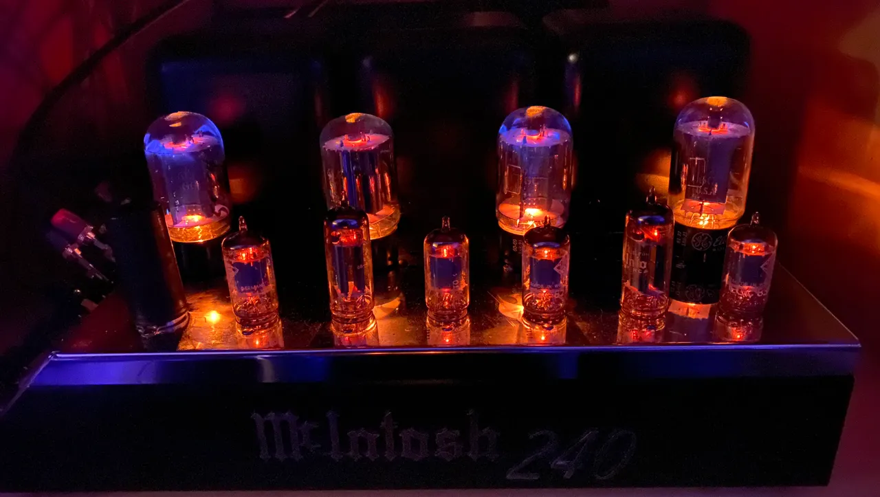
I'll be bi-amping my speakers with the 30s on the top, and the 240 on the bottom. With the solid state rectifier, I get a lot more bass out of the system, and overall I think it sounds amazing.
While I started with a lot of confidence, this restoration turned out to be my most difficult yet! It was worth it, and I wouldn't trade the experience for anything